Warning:Never use this tool on live electrical circuits; it is not insulated against electrical shock. Always use OSHA/ANSI or other industry approved eye protection when using tools. This is not to be used for purposes other than intended. Please read and understand instructions before operating this tool.
Fiber Optic Stripper Introduction
FO 103-Sis for stripping 250 micron buffer coating from 125 micron optical fiber
• Precise hole & V-opening allow for accurate buffer coating removal
• Factory set, requires no adjustment
• Prevents scratching or nicking of optical fiber
• Additional models available upon request

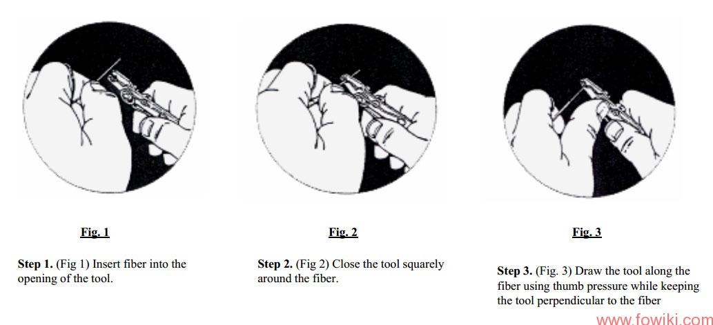
Operation Steps
1.Strip the fiber following steps 1 through 3 below.
2.Clean the stripped fiber and terminate connection per connector splice or connector manufacturer’s instructions.
Note:When stripping extended lengths of buffer coating, it is recommended that several short strips be made to achieve the desired length. This will relieve any pressure caused by the stripped buffer cladding as it accumulates ahead of the cutting edge.
Clean the “V” opening of the tool on a regular basis with 99% Isopropyl Alcohol or an “Alcohol Prep Wipe” to insure proper operation. Failure to do so could cause the fiber to break.
Caution: The fiber optic stripper should not be opened beyond factory pre set limits. Forcing open the tool or bypassing the open position stop will result in loss of factory pre-set calibration and damage the tool.

Fiber Optic Stripper Maintenance Procedures:
Miller FO 103 series tools are factory set and cannot be adjusted or calibrated. The tool may be periodically checked for proper operation. Prior to and during the inspection, the tool may be cleaned with a fine plastic bristled brush to remove debris from the opening. The opening may be cleaned with dry compressed air.
Evaluation Steps
1) Visual Evaluation. Check for damage to the fiber optic stripper such as: rust on the ground surfaces; rough operation of the handles; bent, missing or damaged tool stop or deformation of the adjacent area. The tool must be clean and dry before proceeding with the test procedures.
2) Functional Evaluation. The tool should only be used to strip fiber and the fiber should be subjected to normal qualification tests. The buffered fiber used for these tests should bestandard 125µm fiber. The stripping of fiber should be performed by a trained technician.
3) Optical Evaluation. The opening should be viewed with an optical comparator with a magnification of 50X to 100X power. When performing the evaluations the tool should be held closed with moderate hand pressure and placed flat on a fixture so that the ground faces are perpendicular to the angle of viewing. The opening should form a complete round circle. The diagonal guide/cutting surfaces
should overlap completely. The tool hole opening ranges should adhere to the follow specifications*:
-125µm opening range should be 130 – 175µm
-250µm opening range should be 350 – 450 µm
-2-3mm opening range should be 1.55 – 1.70mm
*Consult factory for custom applications.
It is important to note that the ground surfaces must be held perpendicular to the viewing angle as deviation from this will distort the shape and size of the opening. Fiber Optic Stripper should be tested at least every 6 months or after performing the equivalent of (500) 25mm strips, whichever occurs first. The test period should be reviewed annually to determine if more frequent testing is required.
Fiber Optic Stripper should be kept clean and dry to eliminate surface corrosion. Any tool that fails to meet established standards should be replaced.