For most people, optical fibers are made “special” by what is inside them—the complex optical structures that enable them to preserve polarization in sensors, harness high levels of pump energy in fiber lasers, or even the advanced core chemistries that make them resistant to hydrogen downhole, photo-darkening, or ionizing radiation. But the increasing deployment of optical fiber in harsh environments where glass was never intended to go means that this thinking has to change.
As with most things in life, the word “compromise” features heavily in the selection of coating materials for specific applications—balancing desired performance attributes against the more prosaic handling considerations of ease and speed of application, robustness, ease-of-removal, and even compatibility with any cements or potting compounds the coated fiber may encounter.
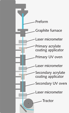
After multiple forays into thermally cured silicone-rubbers and even polyimides encountered varying degrees of success during the late 1970s, the modified, ultraviolet (UV)-cured acrylates that still proliferate today were identified as demanding the fewest compromises when used in the majority of applications. These UV-cured acrylates are easy to apply, even at manufacturing speeds that can now exceed 2000 m/min and preserve the intrinsic high tensile strength of the glass with good protection from both mechanical damage and microbend-induced attenuation (see Fig. 1).

The need to compromise was reduced further in the early 1980s with the arrival of the now almost universal dual-layer coating package—with a soft (typically a Young’s modulus of 1 MPa at room temperature) inner “primary” layer both to enhance practical strength by passivating the glass surface and to provide a cushion from microbending and a hard (1000 MPa) outer “secondary” coating to deliver abrasion resistance and provide a reasonably slick surface with good handling characteristics.
Beyond standard acrylates
By the mid-1980s, efficient, high-speed, and low-cost acrylate coating technology had the vast majority of applications (such as telecommunications) covered, but what of the minority, niche projects? Now that fiber-optic gyroscopes (FOGs) and sensors are mainstream technology, the Faraday effect current sensor is enjoying a renaissance, and optical fibers are being deployed in oil wells, medicine, railway-lines, bridges, dams, and other major infrastructure projects that demand specialty coatings.
For example, FOGs must withstand an environment that is far harsher than any encountered in telecom applications. Hundreds of meters or even kilometers of fiber may be coiled into a volume smaller than the average teacup for operation over an extended temperature range (typically -55°C to +85°C), exposing fiber to stress, microbending, and premature mechanical failure through static fatigue. The fact that these and other fiber sensors also rely on reduced clad 80 μm diameter fiber that is inherently six times less stiff than a conventional 125 μm fiber places even greater emphasis on the overall design of the coating package.
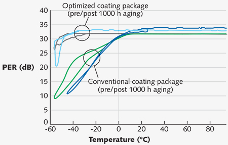
The polarization-maintaining (PM) fibers typically used in FOGs also rely on thermal stress built into the fiber design, increasing the need to protect the fiber from externally generated stress still further. Careful choice of the coating materials, together with the realization that it is the combined stiffness of the fiber/coating composite that determines performance and not simply the selection of the primary with the lowest possible modulus, can reduce stress-transfer to the fiber itself by more than 50%. The impact on performance at sub-zero temperatures is dramatic (see Fig. 2).1
Stable performance is shown for fully stress-optimized versus sub-optimized coating combinations

The acoustic and seismic fiber sensors that are finding increasing application in borehole seismic profiling, frack-monitoring, and permanent reservoir monitoring (PRM) within the oil and gas industry sense the modulated strain in optical fibers that wrap a transducer (fiber-wrapped mandrel). In these applications, efficient strain transfer often dictates the reversion to a single-layer coating to help reduce the hysteresis generated by an over-compliant primary layer, as well as the use of the thinnest possible coating (10–15 μm versus 30–135 μm for acrylates) of a very hard material such as polyimide.
Withstanding high temperature
Harsh environments frequently translate to high temperatures. While most acrylates are rated only to 85°C, they harden slightly upon cooling due to the loss of the plasticizing effect of certain volatiles, and even standard resins may be chemically stable up to 115°C or higher. Fibercore performs accelerated aging tests routinely on standard, acrylate-coated PM fibers at 105°C for 1000 h or more and has found that both the optical performance and mechanical strength remain comfortably within required limits.
Until relatively recently, going much beyond 85°C meant sacrificing the convenience and ease-of-handling provided by acrylates; however, recent years have seen the introduction of a few high-temperature acrylates (HTAs) in both single- and dual-coat formulations. These materials have higher glass-transition ranges (Tgs) around 115°C (50-80°C for conventional secondary acrylates) and resist chemical decomposition until at least 150°C.
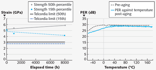
Evaluation of HTA-coated PM Fibers manufactured by Fibercore by a European FOG manufacturer shows that performance is maintained beyond 1000 hours at 150°C continuous exposure and to 180°C for short-term exposures of days to weeks (see Fig. 3). Fiber gyroscopes incorporating these fibers were later deployed successfully in directional drilling trials by a major German construction company.2
High-temperature acrylate (HTA) coatings push the ceiling to 150°C+

Downhole sensing applications are forcing interest in coatings that withstand temperatures of 300°C or higher. Although some users are being converted to the merits of HTAs, the majority of high-temperature/harsh environment applications use polyimide. Although polyimide was evaluated extensively in the late 1970s and early 1980s, material understanding remains many years behind its newer, acrylate rivals.
When applied optimally, polyimides can deliver mechanical protection that extends to 300°C. However, in practice the vast majority of commercially available polyimide-coated fibers start to degrade to some extent from 250°C; specifically, a loss of tensile strength of around 10% may be expected in any polyimide-coated fiber and perhaps 20–30% in carbon-polyimide coated fibers after a few hundred hours exposure to 300°C.
While being very tough at a thickness of 10–15 μm, a typical polyimide coating is between one-sixth and one-tenth of the total thickness of the paint on an average automobile, limiting its abrasion resistance. In fiber manufacture and spooling, it is imperative to insure that all equipment is scrupulously clean and specifically free from metal burrs and silica shards from proof-test breaks.
Besides occasional random mechanical failure, the most frequent criticism of polyimide-coated fiber is difficulty in stripping. Unfortunately, this is a side effect of polyimide’s exceptional chemical stability and the combination of high material strength and strong adhesion to glass. That said, if the application involves continuous exposure to temperatures in the 150–300°C region, polyimide still provides the most practical solution.
Beyond 300°C
For applications beyond 300°C, the only current options are metallized fibers coated in a 15–60 μm layer of gold, aluminum, or copper alloy and capable of raising the operating temperature to 700°C, 400°C, and 500°C, respectively. Unfortunately, the combination of complex, difficult processes, relatively limited applications, and even the rapid rise in the value of gold since 2000 has meant that metal-coated optical fibers are typically regarded as R&D-level products.
To coat fibers with metal, the bare fiber is first drawn through a molten bead, typically of a low-melting-point alloy of the desired metal. Once “primed” in this way, subsequent layers of harder metal may be added to achieve the desired coating thickness—either by drawing the fiber through further molten beads of different alloys or pure metal, or by using the initial layer as a cathode and applying subsequent layers by electroplating (see Fig. 4).
A schematic shows the fiber metal-coating process

The resulting hard metallic coatings make the fiber extremely durable, capable of withstanding extremes of both high and low temperature (minima of -250°C or below are frequently quoted), as well as aggressive liquid chemical and even gaseous environments due to the high levels of hermeticity imparted. The ability to solder the fiber directly onto metallic component packages can also be advantageous.
But once again, these advantages demand compromises. In the case of metals, it is the almost nonexistent stress buffering provided by these very rigid coatings together with high levels of intrinsic microbending that increase minimum attenuation levels from small fractions of a decibel up to 10 dB/km or higher. Nevertheless, in very extreme process monitoring applications in blast furnaces, silicon wafer fabrication, and unconventional oil extraction, metals remain the only viable option.
Reducing fatigue and chemical ingress
Oil and gas fiber sensing is driving interest in carbon coatings. After experimentation with metals and chemical vapor deposition (CVD) of silicon carbide, carbon coatings started to be specified around 1990.
The carbon layer prevents ingress of both water and hydrogen, protecting the fiber from premature mechanical failure through static fatigue and also from increased attenuation due to the presence of both reacted/pendant and interstitial/molecular hydrogen in the core. These hermetic characteristics impart an effectively infinite lifespan on the fiber without degradation of its optical properties—particularly desirable in satellites, spacecraft, and submarine cables.
The carbon-coating process itself is once again very different from those used to apply more conventional polymer-based coatings. The carbon is generated through the pyrolysis of acetylene in a CVD reactor mounted immediately below the drawing furnace so that the retained heat within the fiber drives the reaction. The carbon layer is very thin, typically less than 50 nm but still extremely effective (if pinhole-free) at protecting the fiber surface from chemical ingress and consequent failure through static fatigue.
The combination of the extreme thinness of a typical carbon coating and the brittleness that a thicker layer of carbon would impart means that it can never be considered as a stand-alone coating material and must always be over-jacketed—usually with a UV-cured acrylate (standard or HTA) or polyimide.
When sitting on the sea bed at a constant temperature of a few degrees Celsius, carbon provides an extremely effective barrier to any partial pressure of hydrogen that may be generated by galvanic corrosion or charging batteries, as well as any water that may find its way in via slight leakage or condensation. However, in an oil well, where the temperature may reach or even exceed 300°C and pressures may climb to many tens of atmospheres, absolutely nothing is truly hermetic: hydrogen penetrates the carbon layer, and over 150°C, it does not appreciably slow the process.
For practical deployment, hydrogen resistance must be provided by “hydrogen-passivated” fiber core compositions, rather than by the carbon coating. There is also a general misconception that carbon increases fiber strength, when in reality the carbon layer imparts a micro-roughness to the fiber surface that, when combined with carbon’s intrinsic rigidity, promotes brittle fracture. As a result, the tensile strength of a carbon coated fiber is typically 40–50% lower than that of an equivalent fiber without carbon.
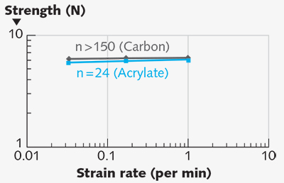
Carbon eliminates the phenomenon of static fatigue by preventing oxygen and hydrogen in the form of O-H from penetrating the fiber surface and accelerating crack growth. In other words, carbon reduces fiber strength appreciably, but can increase lifetime almost indefinitely. Carbon nearly eliminates fatigue (the strength of a carbon-coated fiber is almost invariant with strain rate), whereas with an acrylate coating, the fiber fails at lower loads when the strain rate is reduced, essentially because O-H then has more time to penetrate the surface of the glass and stimulate fracture (see Fig. 5).
Fatigue behavior is shown for carbon-acrylate versus standard acrylate-coated fibers

In conclusion, carbon may not provide the level of universal protection against hydrogen that many think and in reality should be used in conjunction with hydrogen-passivated core compositions. However, it does provide good protection below 150°C and forms an exceptional barrier to water and/or O-H even at higher temperatures.
Thanks to accelerating demand for fiber sensors across an ever-broadening range of applications, fiber-optic coating technology is at last moving forward to take on the challenge of new and invariably, more aggressive environments. Optical fibers are now deployed—routinely at temperatures of 300°C or higher—at high pressure, immersed in hydrocarbons, or under stress conditions that conventionally coated fiber simply could not survive, operating for thousands of hours and potentially even for millennia. In effect, these new, “old” coatings are enabling glass to go where it has not gone before, proving that sometimes beauty really is only skin deep.
References
1. C. Emslie, “Optimisation of coating package design for PM fibers used in high performance fiber optic gyroscopes,” at Inertial Sensors and Systems–Symp. Gyro Technology 2013, Karlsruhe, Germany.
2. U. Probst et al., “Measurement-while-drilling system based on inertial sensors for guided drilling and resurveying applications,” op.cit.
Chris Emslie is CEO of Fibercore, Southampton, England;