Two key thechnology for How an OTDR work?
1. OTDR Introduction
OTDR, short for Optical Time Domain Reflectometer, is a fiber optic test equipment for characterize fiber optic network. It able to detect, locate and measure events at any location on the fiber optic network. The events are displayed as graphic and displayed on the LCD screen. Because it is main device which could provide pictorial record of fiber link, so it is one of the key fiber optic test equipment for fiber and optical network.
The two key technologys for fiber charactering is Rayleigh scatering amd Fresnel Reflection, Rayleigh scattering is for detecting the fiber lengths and the loss for the fiber cable, which is the physical performance of the fiber cable, while Fresnel reflectoins, most used to detect events such as a mechnical connection, fiber splice or joint.
2. Rayleigh Scattering and Back Scatterying
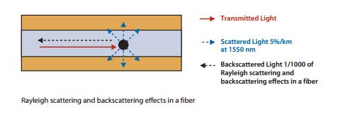
When a pulse injected into the fiber link, some of the light photons scattering in random direction due to microscopic particles, this phenomenon referd as Rayleigh Scattering. It provides amplitued and temporal information along the fiber lengths. among this randome direction particels, some photons reflected in the opposite direction of the input pulse, we refer it as back scattering signal. Please refer to the following figure for more clear view about this two terminology.

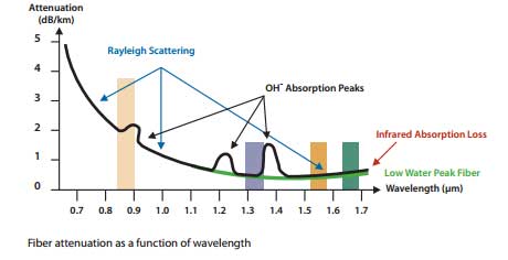
The main loss for the operating fiber is scattering loss, generally in the following windows (or wavelengths 850nm, 1300nm, 1310nm, 1550nm. 1490nm). 1310/1490nm is typically used for FTTx PON network, while 1550nm generally used for Cable TV network, with scattering coefficient of 0.20dB/km will loss about 5% of the transmitted power of a kilometer section of fiber link.
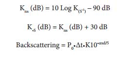
Fiber back scattering factor described as the ration between back scatterd power and the scattered power. and gerenally proportion to the square of the NA (Numerical Aperture). The amount of back scattered power that lauched into the fiber link, is a propotion between the fiber scattering coefficient and the fiber back scattering factor. The nomalized value is calcluated based on 1ns pulse width.

When Kns is 080dB, then for a 1ns pulse width, the back scattering value is less than the incident pulse peak power. It is important to note that -50dB at is 1us is eqal to 080dB at 1ns. The OTDR able to measure the levels of back scattering very precisely.

3. Fresnel Reflection and Back Reflection
Light able to transmit in differnt material, each material with diferent IOR (Index of Refracktive). Thus Fresnel Reflecoin occurs when light transmit ofver different boundary and result different characters of the fiber.

3.1. Power Reflectoin Factor
The following is the formula.
3.2. Back Reflection
Reflection or Backreflection is the amount of light that transmitted to the component
When Pr is the reflected power (W), piis the incident power (W).-14dB is a Theoretical value for light transmited from boundary betwen fiber and air.This value canbe over 4000 times more power for the OTDR detector.
Transition Boundaries Fresnel Reflection
Glass-to-air –14dB
PC-to-PC connector –35to–50dB
APC-to-APC connector –55to–65dB