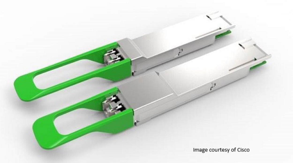
Backwards compatibility is the primary appeal of the QSFP-DD form factor.
The QSFP form factor is today’s industry workhorse for delivering 40 and 100GbE. The “Q” is for “quad” — a nod to the four-channel electrical interface, with each lane running at 25 Gbps for 100GbE. QSFP-DD adapts the same basic concept as its predecessor, but doubles the electrical contact density, via eight differential pairs capable of 50 Gbps each, to achieve 400GbE, while allowing existing QSFP modules to be plugged into the same cage.
Because it is predicated on delivering the bene t of backwards compatibility, QSFP-DD receptacles and cages need to look like and be configured to receive the existing 40 and 100GbE modules. This is accomplished by extending the length of the QSFP-DD module slightly to add an extra recessed row of contacts on both the top and bottom of the connector. The QSFP-DD specification de nes both single-height and stacked configurations of the cage connector system, each supporting QSFP modules with the original rows of contacts, plus supporting QSFP-DD modules via the additional recessed row of contacts.
The connector’s recessed row of contacts is an alternative approach for an I/O electrical interconnect, and it demands significant innovation in the area of signal integrity to meet the 50-Gbps channel requirements currently being defined by the IEEE and the Optical Internetworking Forum (OIF). In addition, the baseline requirement to offer backwards compatibility to existing 40 and 100GbE modules means that the mechanical envelope is limited for possible expansion for the new 400GbE optical and electrical subcomponents.
The QSFP-DD MSA has specified two versions. Type 1 is extended in length only enough to accommodate the recessed extra row of contacts for the electrical interface; Type 2 is extended 15 mm further outside of the equipment faceplate for additional packaging volume inside the module.Thermal management is achieved through improvements to cage design, building on the experience of system designs with QSFP; the module can use riding heat sink technology. External non-integrated heat sinks can be incorporated as part of an optimized system design. The specification’s design is intended to support modules up to at least 12 W. Thermal resistance of a riding heat sink in the past has been at 5 W power levels, and aiming for 10 to 12 W is a significant increase in technical performance.