
Introduction
Current communication data rates in local networks range from 10/100 megabits per second (Mbps) in Ethernet to 1 gigabit per second (Gbps) in fiber distributed data interface (FDDI) and Gigabit Ethernet (GigE). However, the increasing demand for internet protocol (IP)-based services including voice, video, and data requires higher speeds and greater bandwidth, leading to the emergence of 10 GigE local area networks (LANs), especially in the enterprise. The 10 GigE is also emerging in storage area network (SAN) applications, including switch-to-switch links for very high-speed connections between switches inside data centers and between buildings.
Today’s network architecture should be built using 10 Gbps technology to ensure that the network is scaleable and allows easy and cost-optimized upgrades.
This white paper should provide an understanding of 10 GigE network complexities, including the difference between multimode and single-mode fiber, limitations and demands associated with 10 GigE LAN environments, and how the complexities can impact future requirements for high-speed networks. It will also review 10 GigE acceptance testing, including a review of test equipment used to qualify current and future local networks.
Understanding the Difference between Multimode or Single-Mode Fiber Classifications
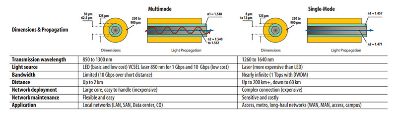
Two classifications of fiber are used in fiber optic networks: single-mode and multimode. Single-mode fiber has a small core size of 8 to 12 microns (µm) according to international standards and allows light transmission in only one mode, or ray of light. Single-mode fiber can transmit large bandwidth over long distances (10 Gbps, 40 Gbps with proper dispersion compensating components), so it is generally installed in access, metro, and long-haul networks. On the other hand, single-mode fiber requires expensive light sources and alignment devices that can inject light precisely in the small core of single mode fibers. This makes single-mode network construction sensitive and costly.
Multimode fiber has a much larger core than singlemode (50, 62.5, or higher µm), allowing light transmission along multiple paths (modes). This kind of propagation generates disturbances called modal dispersion due to the different speed of each mode. Consequently, the signal attenuation (loss in power) is higher, the bandwidth is limited over distance (10 Gbps over 300 meters), and IEEErecommended maximum distances do not exceed 2 kilometers. Multimode fibers are generally installed in premises and enterprise networks. They are much less sensitive to bending constraints than singlemode fibers, and because the large core in multimode causes it to capture light easily, coupling multimode fibers to light sources or other fibers does not require expensive transmitters or connectors, which makes network deployment and maintenance flexible and cheaper than singlemode.
Multimode or Single-Mode in Premises?
The continuous demand for higher communication data rates has led network designers to consider single-mode fibers as a future-proof choice in premises and even for short distances. However, multimode fibers are well-dimensioned to carry 10 Gbps up to 300 meters (m), which applies to the long backbone in most enterprise environments. Considering the cost savings compared to singlemode networks, ultimode cabling should be considered for premises networks. Furthermore, multimode cabling offers great flexibility in terms of daily maintenance due to the ease of extending, moving, or changing connections.
50 µm versus 62.5 µm Multimode Fibers
When optical transmission appeared in the field in the 1970s, optical links were based on 50 µm multimode fiber waveguides and light emitting diode (LED) light sources for both short and long ranges. In the 1980s, laser-powered single-mode fibers appeared and became the preferred choice for long distance, while multimode waveguides were positioned as the most cost-effective solution for local networks and for interconnecting building and campus backbones over distances of 300 to 2000 m.A few years later, emerging applications in local networks required higher data rates including 10 Mbps, which pushed the introduction of 62.5 µm multimode fiber that could drive 10 Mbps over 2000 m because of its ability to capture more light power from the LED. At the same time, its higher numerical aperture eased the cabling operation and limited signal attenuation caused by cable stresses. These improvements made 62.5 µm multimode fiber the primary choice for short-range LANs, data centers, and campuses operating at 10 Mbps.
Today, Gigabit Ethernet (1 Gbps) is the standard and 10 Gbps is becoming more common in local networks. The 62.5 µm multimode fiber has reached its performance limits, supporting 10 Gbps over 26 m (maximum). These limitations hastened the recent deployment of a new design of economical lasers called vertical cavity surface emitting lasers (VCSELs), and of a small core of 50 µm fiber that is 850 nm laser-optimized.
Demand for increased data rates and greater bandwidth has further led to widespread use of 50 µm laser-optimized fibers capable of offering 2000-MHz .km bandwidth and a high-speed data rate over long distance. Trends in local network design are to cable backbone segments with such fibers in order to build a more future-proof infrastructure.
Data Communication Rate and Transmission Lengths
When installing fiber cables, it is important to understand their capabilities in terms of bandwidth along the distance to ensure that installations are well-dimensioned and support future needs. As a first step, it is possible to estimate the transmission length according to the ISO/IEC 11801 standard table of recommended distances for networking
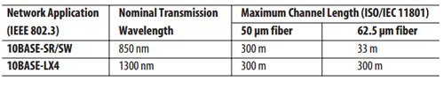
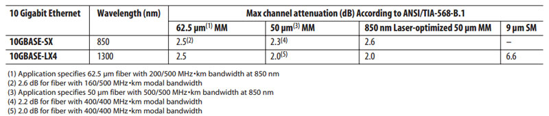
Ethernet. This table assumes a continuous cable length without any devices, splices, connectors, or other loss factors that affect signal transmission: As a second step, the cabling infrastructure should respect maximum channel attenuation to ensure a reliable signal transmission over distance. This attenuation value should consider end-to-end channel losses, including:
– The fiber attenuation profile, corresponding to 3.5 dB/km for multimode fibers at 850 nm and corresponding to 1.5 dB/km for multimode fibers at 1300 nm (according to ANSI/TIA-568-B.3 and ISO/IEC 11801 standards).
– Splices (typically up to 0.1 dB loss), connectors (typically up to 0.5 dB loss) and other commonly occurring losses.
Certifying a Fiber Cabling System
The 10-GigE applications in premises networks are challenging and require a high-performance cabling infrastructure. Therefore, network owners who need an overview of their fiber plant at the time of construction require cable certification to ensure that the physical infrastructure can support expected performances in terms of speed and bandwidth.
Required measurements
According to ANSI/TIA/EIA-568-B.3 standard, values of optical attenuation, return loss, propagation delay, and polarity are mandatory for fiber compliance and, therefore, require test validation. For acceptance testing, only optical attenuation measurements and polarity test are mandatory with the other measurements being voluntary.
In addition, fiber cable length must be either calculated or measured for both compliance and acceptance testing.
The values, their parameters, and test methods used to validate them are detailed below.
Optical attenuation
The first step of fiber certification consists of calculating the total attenuation along a fiber link. This attenuation, called link loss budget, equals the sum of fiber loss, connector(s) loss, and splice(s) loss. Optical attenuation is measured using an optical source and a separate power meter or using an optical loss test set (OLTS) that combines an optical source and a power meter. The first step in this test process is to take a reference power measurement. Then, one end of the fiber is connected to the power meter and the other to the optical source. The total loss of the link is measured and compared to values allowed by the standard. For 10-GigE applications, maximum acceptable channel attenuation when designing a cabling system is specified in ANSI/TIA-568-B.1 and IEC 11801 standards. For specific values, refer to the tables presented in the Data Communication Rate and Transmission Lengths sections.
Once a fiber link budget has been calculated, it may be necessary to troubleshoot problems with the fiber, especially if the measured attenuation does not meet the standardized limitations. Use an optical time domain reflectometer (OTDR) for troubleshooting. OTDRs measure the total loss of an optical link but they also locate bends, measure and locate high splice losses, high connector losses, and high connector reflectance.
After technicians locate link losses, they can then fix significant loss sources (by repair, connector cleaning, or other methods) to decrease the total link budget and meet recommended value standards. When using an OTDR as a single-ended tester, all tests can be performed from any test point location.
Return Loss
Optical return loss (ORL) is the total accumulated light reflected back to the source along the telecommunication link. ORL can degrade the stability of the laser source and can, therefore, directly increase the bit error rate (BER).
In order to meet system manufacturer specifications for error-free transmission, consider ORL measurements during system installation or system upgrade processes for comparison with allowable limits.
The ORL is expressed in positive decibels (dB) and defined as the logarithmic ratio between the transmitted power (Pi) and the received power (Pr: back-reflection + back-scattering) at the fiber origin:
ORL = 10 log (Pi/Pr)
Such measurements are commonly conducted with an optical continuous wave reflectometer (OCWR), an instrument composed of a laser, a power meter, and a coupler, or with an OTDR.
Propagation Delay
Propagation delay is the time required for data to travel from its transmission point to destination. It can be calculated if considering the length of optical channels under test. Some applications require knowledge of the propagation delay of optical fiber channels to ensure compliance with the end-to-end delay requirements of complex networks consisting of multiple cascaded channels. As part of the test process, JDSU OTDRs automatically display propagation delay values.
Polarity Test
A polarity test checks the continuity of an optical channel from end to end.
Polarity tests generally are conducted with a visual fault locator (VFL). A VFL couples visible light into
the fiber to allow visual tracing.
Polarity tests can also employ a source and a power meter or an OTDR using a receiver launch cable.
White Paper: Cabling and Test Considerations for 10 Gigabit Ethernet (10 GigE) Local Area Networks 6
Screenshot of JDSU MTS-6000 platform with OTDR
Westover Scientific FFL-100 Visual Fault Locator
Fiber Optic Inspection
In high data rate applications, optical attenuation sources must be eliminated to ensure required performance. Dirty fiber optic termination points and connectors can generate significant signal losses. All connections and adapters must be cleaned at the optical test points prior to taking measurements. Conduct connector inspections with video inspection probes or a fiber inspection microscope that can quickly check for connector cleanliness.
Report
The last step in fiber certification is to properly document the measurements of the fiber plant. Organize data collection and analysis in a way that provides easy and clear access to the important information. Powerful fiber analysis software, such as JDSU FiberCable software, helps reduce the time dedicated to processing a large quantity of analysis data as part of the quality of service (QoS) process. OVIP-400 Video Inspection Probes Certification Report generated by JDSU OFS-200 Fiber Cable software
Conclusion
In local networks, the qualification of the cabling infrastructure has always been recommended. Today, the data rate requirements are very high, pushing multimode technology to its limits because it is necessary to properly and proactively qualify networks to ensure the delivery of 10-GigE applications. Field instrument manufacturers provide optimized solutions that test this kind of network. For example, the JDSU T-BERD/MTS-6000 offers an OTDR that provides qualification of all parameters defined in international standards, such as optical attenuation, return loss, propagation delay, and polarity test. A microscope option can be included to easily verify and qualify connectors along the optical link. Installers use instruments like the T-BERD/MTS-6000 to ensure and guarantee optimal QoS. Additional options such as the previously mentioned FiberCable software offer the possibility to document measurements and provide network managers with detailed, accurate insight into the fiber plant at the time of construction.