
A concatenated link usually includes a number of spliced factory lengths of optical fibre cable. The requirements for factory lengths are given in clauses 5 and 6. The transmission parameters for concatenated links must take into account not only the performance of the individual cable lengths but also the statistics of concatenation.
The transmission characteristics of the factory length optical fibre cables will have a certain probability distribution which often needs to be taken into account if the most economic designs are to be obtained. This appendix should be read with this statistical nature of the various parameters in mind.
Link attributes are affected by factors other than optical fibre cables, by such things as splices, connectors and installation. These factors cannot be specified in this Recommendation. For the purpose of link attribute values estimation, typical values of optical fibre links are provided in the tables below. The estimation methods of parameters needed for system design are based on measurements, modelling or other considerations.
1.1 Attenuation
The attenuation, A, of a link is given by:
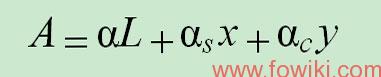
where:
l typical attenuation coefficient of the fibre cables in a link;
ls mean splice loss;
x number of splices in a link;
lc mean loss of line connectors;
y number of line connectors in a link (if provided);
L link length.
A suitable margin should be allocated for future modifications of cable configurations (additional splices, extra cable lengths, ageing effects, temperature variations, etc.). The above equation does not include the loss of equipment connectors. The typical values found in clause I.5 are for the attenuation coefficient of optical fibre links. The attenuation budget used in designing an actual system should account for the statistical variations in these parameters.
1.2 Chromatic dispersion
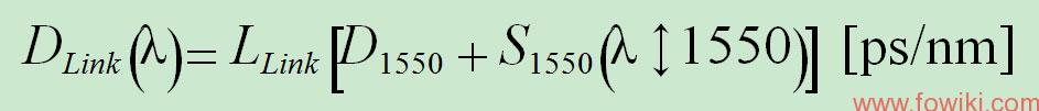
The chromatic dispersion in ps/nm can be calculated from the chromatic dispersion coefficients of the factory lengths, assuming a linear dependence on length, and with due regard for the signs of the coefficients (see clause 5.10).
When these fibres are used for transmission in the 1550 nm region, some forms of chromatic dispersion compensation are often employed. In this case, the average link chromatic dispersion is used for design purposes. The measured dispersion in the 1550 nm window can be characterized within the 1550 nm window by a linear relationship with wavelength. The relationship is described in terms of the typical chromatic dispersion coefficient and dispersion slope coefficient at 1550 nm.
Typical values for the chromatic dispersion coefficient, D1550, and chromatic dispersion slope coefficient, S1550, at 1550 nm are found in Table I.1. These values, together with link length, LLink, can be used to calculate the typical chromatic dispersion for use in optical link design.
1.3 Differential group delay (DGD)
The differential group delay is the difference in arrival times of the two polarization modes at a particular wavelength and time. For a link with a specific PMD coefficient, the DGD of the link varies randomly with time and wavelength as a Maxwell distribution that contains a single parameter, which is the product of the PMD coefficient of the link and the square root of the link length. The system impairment due to PMD at a specific time and wavelength depends on the DGD at that time and wavelength. So, means of establishing useful limits on the DGD distribution as it relates to the optical fibre cable PMD coefficient distribution and its limits have been developed and are documented in [b-IEC/TR 61282-3] and are summarized in Appendix IV of [ITU-T G.650.2].
The metrics of the limitations of the DGD distribution follow: NOTE – The determination of the contribution of components other than optical fibre cable is beyond the scope of this Recommendation, but is discussed in [b-IEC/TR 61282-3].
Reference link length, LRef: A maximum link length to which the maximum DGD and probability will apply. For longer link lengths, multiply the maximum DGD by the square root of the ratio of actual length to the reference length. Typical maximum cable length, LCab: The maxima are assured when the typical individual cables of the concatenation or the lengths of the cables that are measured in determining the PMD coefficient distribution are less than this value. Maximum DGD, DGDmax: The DGD value that can be used when considering optical system design. Maximum probability, PF: The probability that an actual DGD value exceeds DGDmax.
1.4 Non-linear coefficient
The effect of chromatic dispersion is interactive with the non-linear coefficient, n2/Aeff, regarding system impairments induced by non-linear optical effects (see [ITU-T G.663] and [ITU-T G.650.2]). Typical values vary with the implementation. The test methods for non-linear coefficient remain under study.
1.5 Tables of common typical values
The values in Tables I.1 and I.2 are representative of concatenated optical fibre links according to clauses I.1 and I.3, respectively. The implied fibre induced maximum DGD values in Table I.2 are intended for guidance in regard to the requirements for other optical elements that may be in the link.
NOTE – Cable section length is 10 km except for the 0.10 ps/ km /> 4000 km link, where it is set to 25 km, the error probability level is 6.5 × 10⁻⁸.