
As fiber links support higher-speed network bandwidths with increasingly stringent requirements, it’s becoming more important to ensure your backbone links meet tightening loss standards. The need for higher data transmission capacity continues to increase as network applications grow and expand. These higher transmission speeds demand cabling that delivers increased bandwidth support. This test and troubleshooting guide outlines cabling performance requirements, field testing, certification and troubleshooting techniques and instruments to ensure the installed optical fiber cabling supports high data rate applications such as 1 and 10 Gigabit per second (Gbps) Ethernet, Fibre Channel and 40 and 100 Gbps Ethernet applications.
Fiber verification testing (including end-face inspection and cleaning) should be a part of technician’s standard operating procedures. Throughout the cable installation process and before certification, you should measure the loss of cabling segments to ensure the quality of the installation workmanship. This test is normally done with a Light Source and Power Meter (LSPM) test set. Fiber verification test tools are typically less expensive tools; they’re also effective in troubleshooting links. A quick inspection of the end-to-end link loss may indicate whether or not the optical fiber cable is suspect or whether other network functions are the cause of the malfunction.
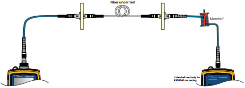
An LSPM determines the total light loss along a fiber link by using a known light source at one end and a power meter at the other. But, before the test can be done, measure and record a reference power level from the source to set a baseline for the power loss calculation. After this reference is established, plug the meter and source into the opposite sides of the fiber link to be tested. The source emits a continuous wave at the selected wave length. On the distant end, the power meter measures the level of optical power it receives and compares it to the reference power level to calculate the total amount of light loss (Figure 1). If this total loss is within the specified parameters for the link-under-test, the test passes.
A loss budget should be well established and used as a benchmark during cabling installation. If this verification testing is performed during installation, you can expect that yield will increase and certification testing will go more smoothly. Historically, LSPM test sets require manual calculations and subjective interpretation by experienced technicians. However, newer instruments automatically compare power measurements to set references, eliminating the time-consuming loss calculations.
Using an LSPM set to verify end-to-end loss is convenient. But, it doesn’t indicate where trouble areas are. Failures can be difficult to locate and analyze. Even when the loss is within a specified threshold, the LSPM set doesn’t provide any warning or indication of where a defect or problem may be. In other words, although an entire link may pass, it’s possible individual splices or connections within it may fail industry specifications. This creates a potential problem in the future during adds, moves or changes where multiple dirty connectors might be grouped together and result in a failure. An Optical Time Domain Reflectometer (OTDR) can pinpoint locations (connections) displaying a high loss or reflectance.