
OTDR used in fiber network acceptance test
We will use the manual method of OTDR operation. Start the OTDR and select the correct wavelength and refractive index for the test. Set the OTDR’s measurement mode to “Two Point Attenuation”. In this mode, the OTDR allows you to set markers at any two points on the backscatter trace and display the attenuation of the region between the markers in either dB or dB per kilometer.
For an acceptance test, set the first marker at the beginning of the trace after the initial tail of the dead-zone and the second marker at the end of the trace. The results will display as dB/km at a specific wavelength being tested. Set the OTDR to “Real-time Mode” and adjust its range, pulse width, and zoom settings so that the entire fiber span is visible on the screen. If no trace displays, there may be too much loss in the pigtail splice. In this case, adjust the fibers in the temporary mechanical splice. Be sure that the cleave length is correct and that the fibers are centered in the splice.
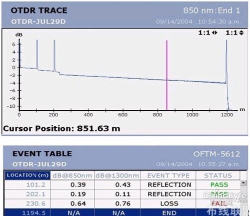
In real-time mode, the trace may appear noisy. Start the OTDR’s averaging mode to reduce noise and clean up the trace. After averaging is complete, the event table will show reflective events at the OTDR port and at the end of the fiber. The trace should appear linear with no abrupt interruptions that would indicate a break or other fault in the fiber. After the dead zone, the straight line will have a very gentle slope indicating the attenuation of the fiber span.
Marker placement is extremely important when making any OTDR measurement. Select the “A” marker and use the arrow keys to place it immediately following the dead zone at the OTDR’s connector.
The tail of the dead zone is shaped somewhat like a ski slope. The exact point where this slope becomes a straight line is the point where the marker will be placed. The far end of the fiber could be represented by a spike, or less commonly, by a roll-off. In either case, the “B” marker must be placed at the exact point where the backscatter trace ceases to be a straight line. To correctly place the second marker, use the zoom controls on the OTDR for increased resolution.
The OTDR will display the distance from the OTDR connector to the end of the fiber as well as the total loss of the span in dB or the loss per kilometer. Use the data storage features of the OTDR to save the trace using a unique file name. If using a dead-zone box, the length must be subtracted from the length measurement.
When measuring the other fibers in the cable, the end reflection should be located at the roughly same point. The presence of shorter fibers implies that the fiber is damaged or stressed within the cable structure and will require further investigation. It could also be caused by cable structures with inner and outer rows of buffer tubes. The inner buffer tubes would have a shorter fiber length than those in the outer rows. In this case, an index of refraction adjustment must be made for both inner and outer rows and the adjustment documented.
For each fiber, make a note of the total length and dB per kilometer for each test wavelength on the acceptance test form. It is also important to test each fiber at the wavelengths designed for the fiber type. For multimode fiber, this is 850 and 1300 nanometers, and for single-mode fibers, both 1310 and 1550 nanometers. Refer to the testing specifications and note if they pass or fail. In addition, make note of the sequential markings at both ends of the cable, as well as the adjusted value of refractive index.
After each fiber has been tested, trim back 50 percent of the exposed length. This indicates that it has been tested, but allows re-testing if necessary. After all the fibers have been tested, count your fiber traces in the OTDR’s memory to ensure that all fibers have been documented. Then, cut back the remaining lengths of exposed fiber and properly reseal the cable ends.
This article reviewed how to perform an acceptance test and how to place OTDR markers manually for accurate results. However, most users will rely on the OTDR’s automatic measurement functions, which quickly display length, losses, and reflection values for the fiber span. In the case of an acceptance test, the key points to document are the total length of the fiber, the total loss of the fiber in dB, and the loss of the span for each test wavelength in dB per kilometer.