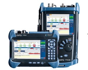
OTDR used in Fiber Optic Acceptance testing – 1
Fiber optic acceptance testing ensures that any new cable matches the optical and physical requirements of the planned application. This testing should be performed upon delivery of the cable, prior to its installation.
It is important that the operator knows the specifications in order to properly test against them. These specifications include the cable’s length, its fiber count, the acceptable loss in dB per kilometer, the total loss, the operating wavelength, and the fiber type and manufacturer. This process also provides an opportunity to obtain and store OTDR waveforms in the system documentation for future maintenance or restorations.

Always carefully examine the cable reel for physical signs of shipping damage. Look for evidence that indicates the cable has been subject to unacceptable amounts of stress.
The reel will include some form of cable documentation. A copy of this information should be attached to the acceptance test form. These documents generally contain traceability information, as well as optical test data difficult to acquire in the field. For example, a multimode fiber reel’s documentation would include information on the fiber’s bandwidth, while a single-mode fiber reel would provide test data related to the various types of optical dispersion.
This documentation form also lists the fiber’s index of refraction, as documented by the fiber’s manufacturer. This number should be not be used for the index of refraction in the OTDR because it does not include the cable’s helix factor, which is a measure of the difference in fiber versus cable sheath length. The technician must compensate for the extra fiber slack by adjusting the OTDR’s refractive index setting so that OTDR distance readings match the sequential markings on the cable jacket. The acceptance test is the best opportunity to make these adjustments prior to cable installation.
One important consideration in testing is to ensure a good launch condition that couples the maximum amount of light from the OTDR into the fiber. Poor launch conditions result in greatly reduced distance-measurement capability and possible measurement errors. Before any tests can be made with the OTDR, it must be properly terminated to the fiber to be tested.
For installed spans, linking the OTDR to the span under test requires a hybrid patch cord. Most OTDRs have an internal ultra physical contact (UPC) spherical polish, but some reflection-sensitive systems use the angled physical contact (APC) polish. The hybrid patch cord addresses both connector type and connector polish issues. Always clean the end face of the plug prior to mating to the OTDR.

There are two methods of terminating a fiber. The first method uses a bare-fiber adapter, which consists of a plug body that grips the fiber to be tested. The design of the bare-fiber adapter is such that the fiber can pass completely through the adapter body and damage the optical port. Because of this, the barefiber adapter must never be connected directly to the OTDR. Instead, the adapter should be used with a short patch cord and mating adapter sleeve to isolate damage from the OTDR’s port.
The second method uses a pigtail with a reusable mechanical splice, which allows easy mating of the fibers to be tested with the OTDR. The Norland reusable mechanical splice has been used for decades for testing bare fibers. It features a glass body that internally holds and aligns two fibers. The splice is filled with a refractive index matching fluid to reduce reflections. To make the connection, strip and cleave both of the fibers to be tested, then insert and center both into the mechanical splice to complete the termination.
For the cable to be tested, prepare the end of the cable by stripping away the outer jackets, armor (if present), and buffer tubes to a distance of approximately one meter. Clean all of the fibers and organize them based on the industry standard color code. Strip, clean, and cleave the first test fiber and insert it into the other end of the mechanical splice so it lightly butts against the pigtail fiber.