
End face geometry is an essential characteristic of repeatable and reliable optical fiber connections. Overall performance of fiber optic connectivity depends on the mechanical characteristics that control alignment and physical contact of the fiber cores. End face geometry parameters for MPO/MTP connectivity include:
- Angle of the polish – Horizontal or X axis (RX and GX)
- Angle of the polish – Vertical or Y axis (RY and GY)
- Fiber Protrusion Height (H)
- Maximum Fiber Height Differential Among all Fibers (HA)
- Maximum Adjacent Fiber Height Differential (HB)
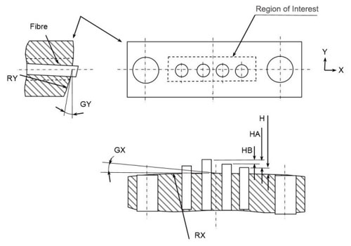
Figure 1: End face geometry parameters as defined by IEC PAS 61755-3-31 (Note: Four fibers shown for clarity)
Figure 1 below shows the end face geometry parameters for MPO/MTP connectors as defined by IEC PAS 61755-3-31. All samples were subjected to an optical inspection to determine end face quality (contamination, scratches and defects) and then subjected to end face geometry analysis to confirm standards compliance. Samples were also subjected to end face geometry analysis per Siemon’s more stringent specification.
Table 1 shows the results of the end face quality testing and geometric parameter compliance for the MPO/MTP Trunk Assemblies. Only two of the manufacturers had product that was compliant with the IEC standard for end face geometry—Manufacturer A2 and Siemon. The other three manufacturers had four or more failures, most of which can be attributed to a lack of fiber height control during the polishing process at the manufacturing stage.
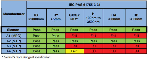
Table 1: End Face Geometry Test Results for MPO/MTP Trunk Assemblies
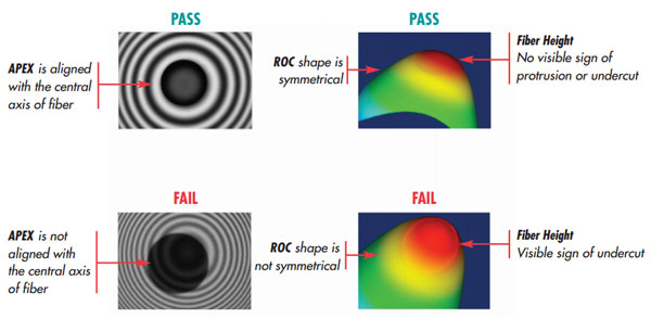
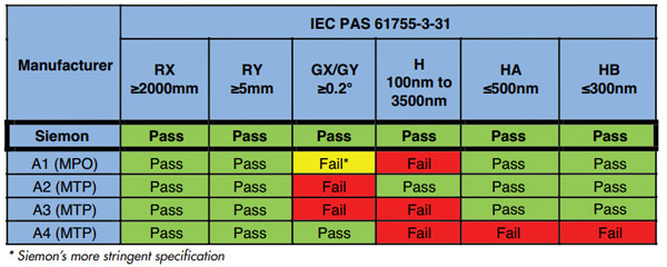
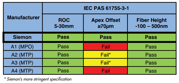
Tables 2a and 2b show the results of end face quality testing and geometric parameter compliance for the MPO/MTP-to-LC Hybrid assemblies. Each of the sample hybrid assemblies was tested for end face geometry for both the MPO/MTP (Table 2a) and LC connector (Table 2b) ends. It is important to note that end face geometry testing for LC connectors differs from that of MPO/MTP connectors and includes the following parameters as described below and shown in Figure 2:
- Radius of Curvature (RoC): Measures the end-face spherical condition to ensure proper fiber to connector compression. The ROC range that allows for maximum connector performance is 7 to 25mm.
- Apex Offset: Measures the distance between the center of the fiber and the actual highest point of a polished connector. An excessive Apex Offset contributes to high insertion loss and reflection.
- Fiber Height: Measures the distance the fiber is extended out of or recessed into the ferrule, which must be in the -100nm to 50nm range.
For the hybrid assemblies, Manufacturer A4 in particular had difficulty maintaining control of fiber height and differential fiber height for the MPO/MTP connector. Overall, end face geometry for the LC connectors on the assemblies was standards compliant with the exception of Manufacturer A1 and A4 for Apex Offset.
Source: SIEMON whitepaper